Types of Threads
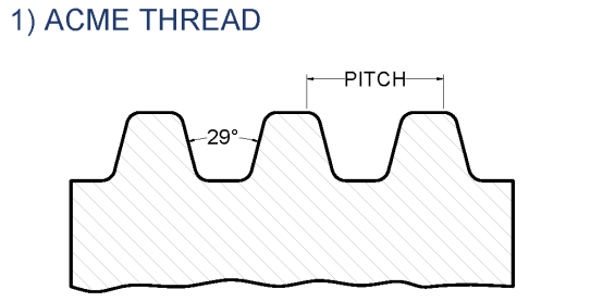
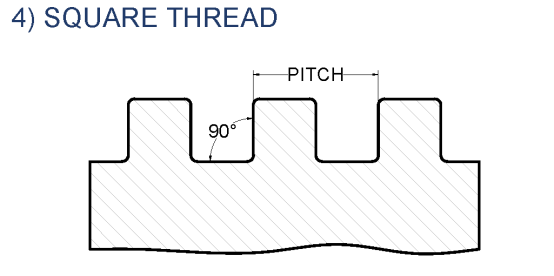
The acme thread form, established over 100 years ago, replaced
square thread screw, which had straight-sided flanks and were difficult to manufacture. There are three main classes of acme thread forms: general purpose (G), centralizing (C), and stub acme.
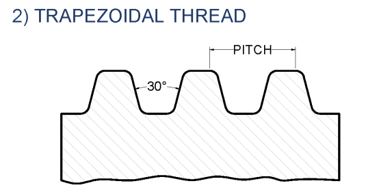
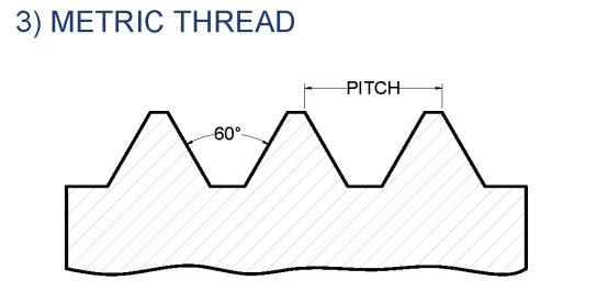
The General Purpose and Centralizing thread forms have a nominal depth of thread of 0.50×Pitch and have a 29° included thread angle. Trapezoidal thread forms have a 30° included thread angle. Metric thread forms have a 60° angle. Compared to general-purpose thread forms, centralizing
threads are manufactured with tighter tolerances and reduced clearance on the major diameter. Stub acme threads follow the same basic design, but have a thread depth less than one half the pitch.
If an acme nut is side loaded with a radial load, a “G” class will
“wedge” when the nut thread flanks come in contact with the screw thread flanks. To prevent wedging, less clearance and tighter tolerances are allowed between the major diameter of the nut and the major diameter of the screw. CAUTION - Although a side load will not cause a centralizing thread
to wedge, the nut is not designed to operate with a side load such as a pulley, drive belt, etc.